The Hydrocube
August 3, 2025
My former colleague, Petr Karnakov, and I have developed a novel method for path planning of objects when the dynamics of a system are known. The method is presented in details in our 2025 publication in Physical Review Letters (also available on arxiv). The method beats reinforcement learning in several benchmarks, but we had only tested this in simulations so far (we are computational scientists after all).
One day our PI suggested that we apply the method to a physical setting, and he pointed out that there was a robotics challenge here in Boston, about two months later, organized by MassRobotics, called form and function challenge. We decided to participate and built a robot, the Hydrocube.
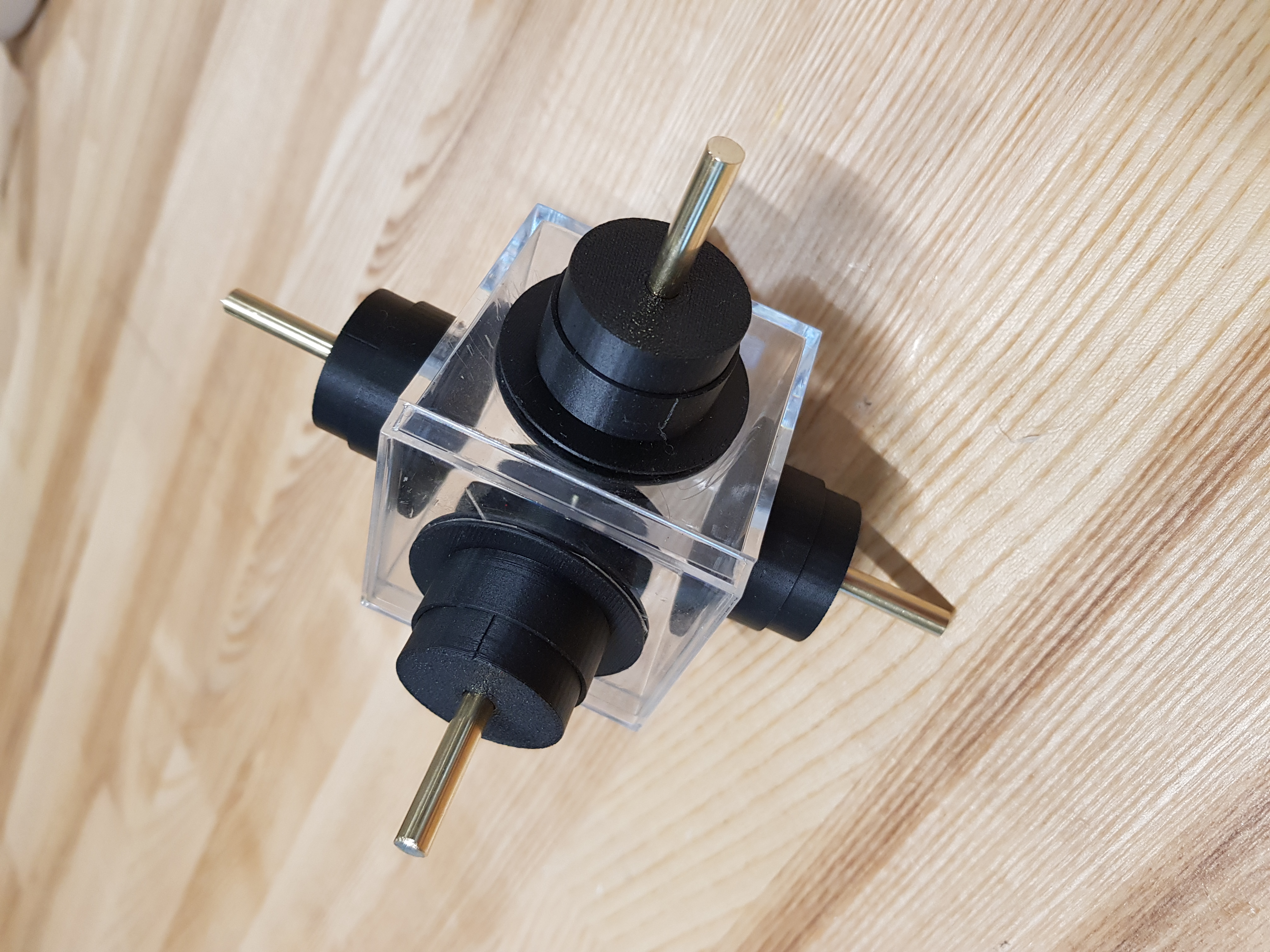
The Hydrocube is a device that transports small objects suspended in a liquid towards prescribed targets in three dimensions. The transport is realized by creating a flow in the chamber with the help of 5 rotating disks. The method we developed learns, in simulations, how to choose the rotation speed of the disks given the current position of the beads and their targets.
Therefore, the device required the following components:
- a cubic chamber filled with a liquid;
- 5 rotating disks, at the bottom and sides of the chamber;
- 5 motors to independently control each disk;
- cameras, placed at the top of the chamber, to estimate the current position of beads;
- a device to control the disks, and electronics between this device and the motors;
- the cameras and the device were connected to a laptop, which hosts the control algorithm.
Here I want to share some snapshots of what happened during the building process of the Hydrocube.
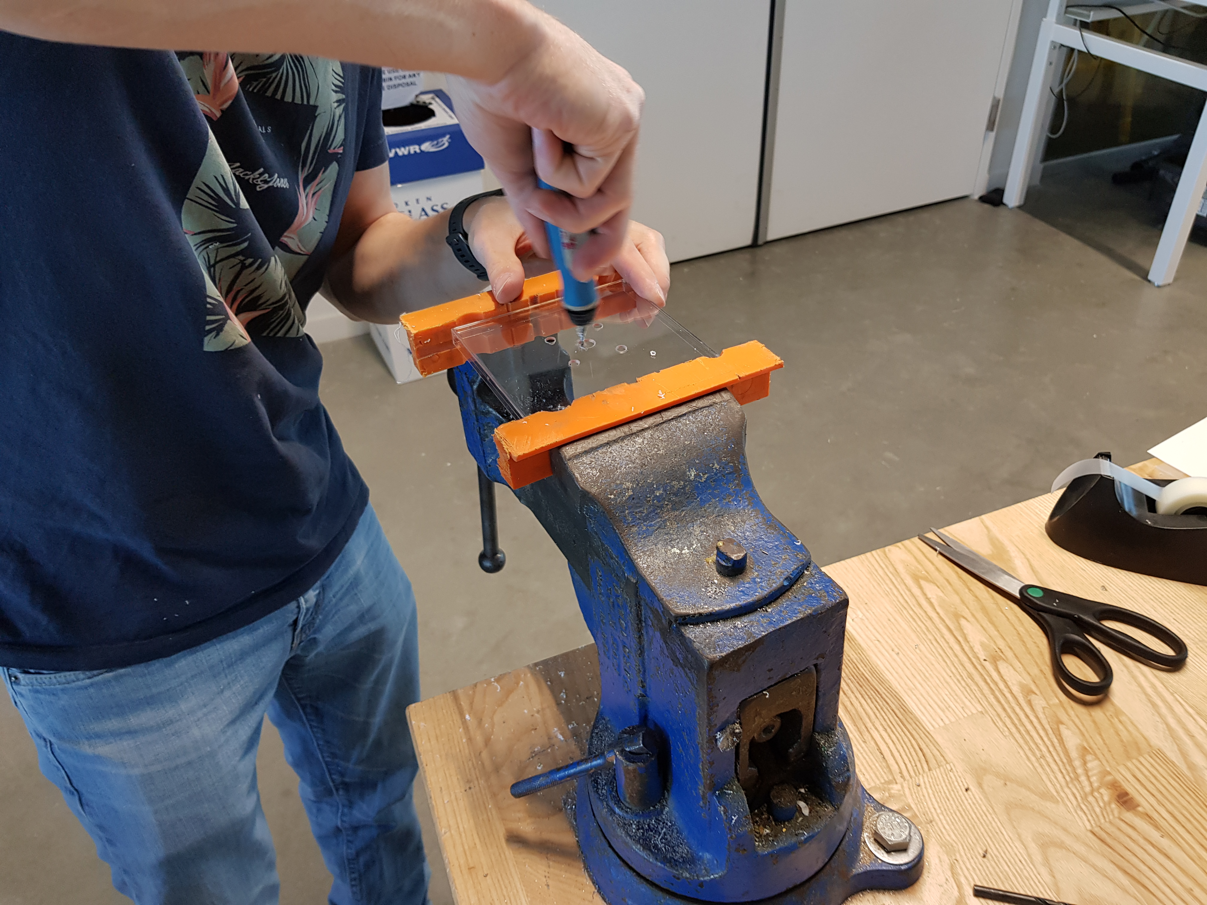
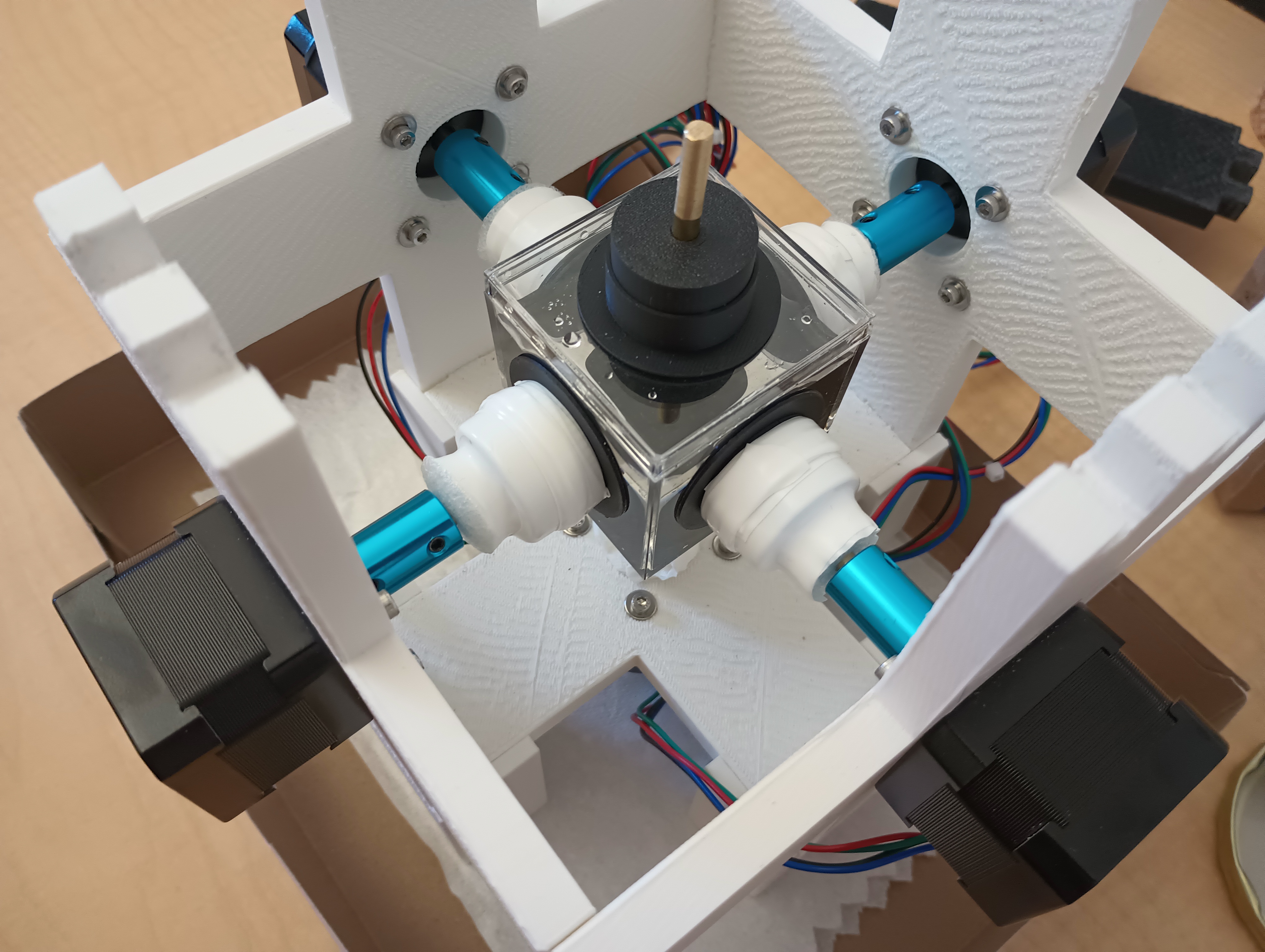
The chamber and rotating disks
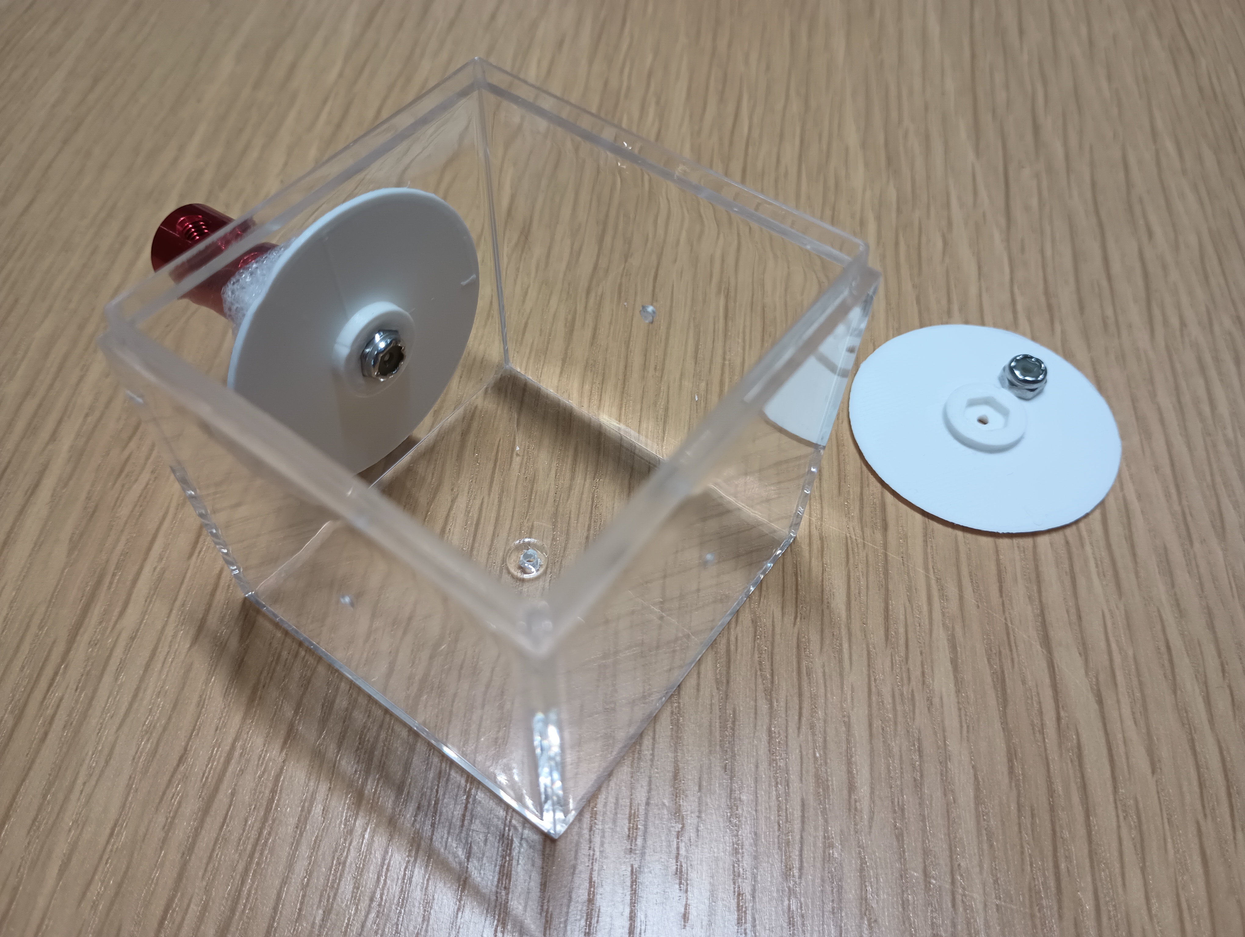
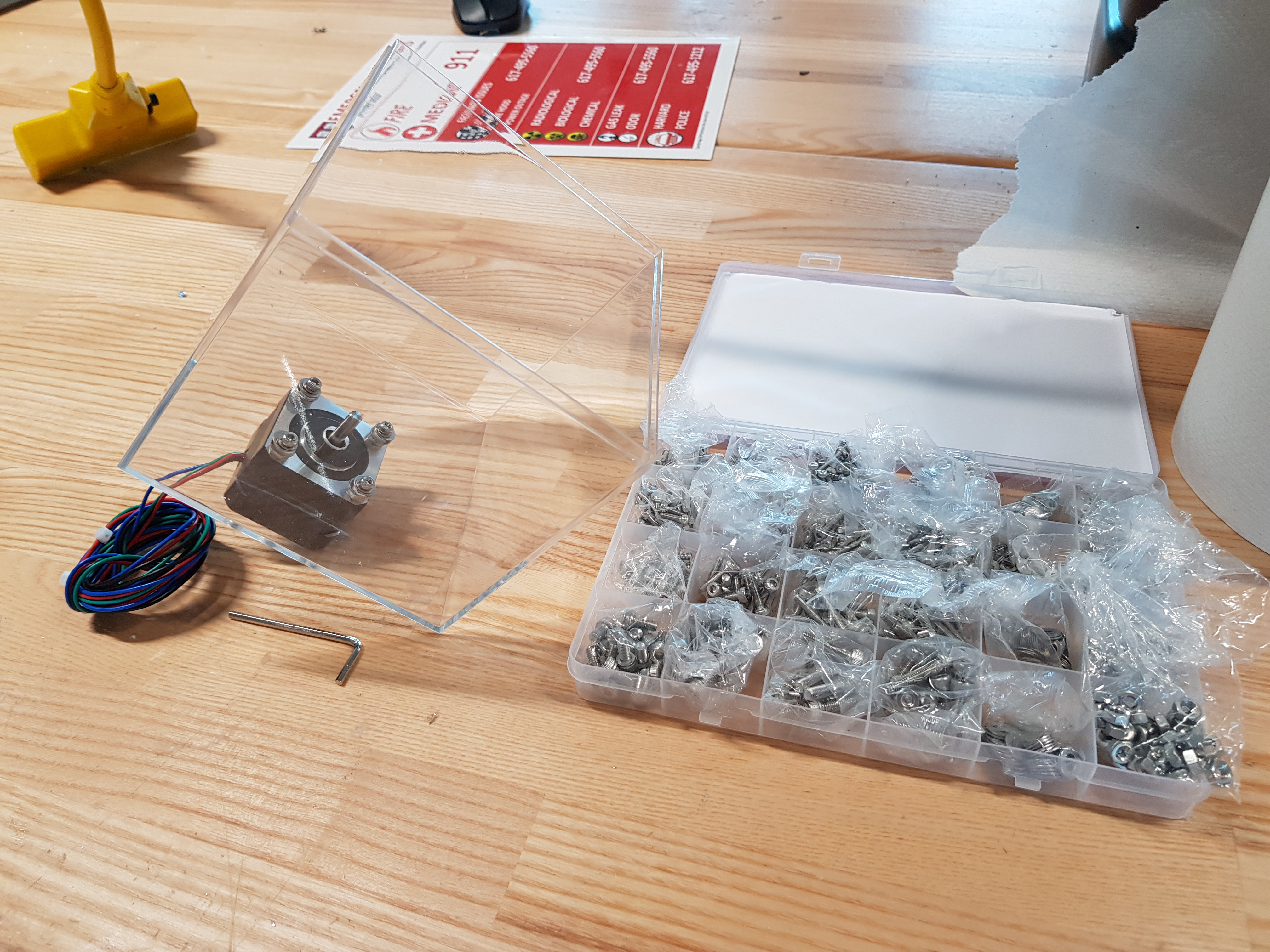
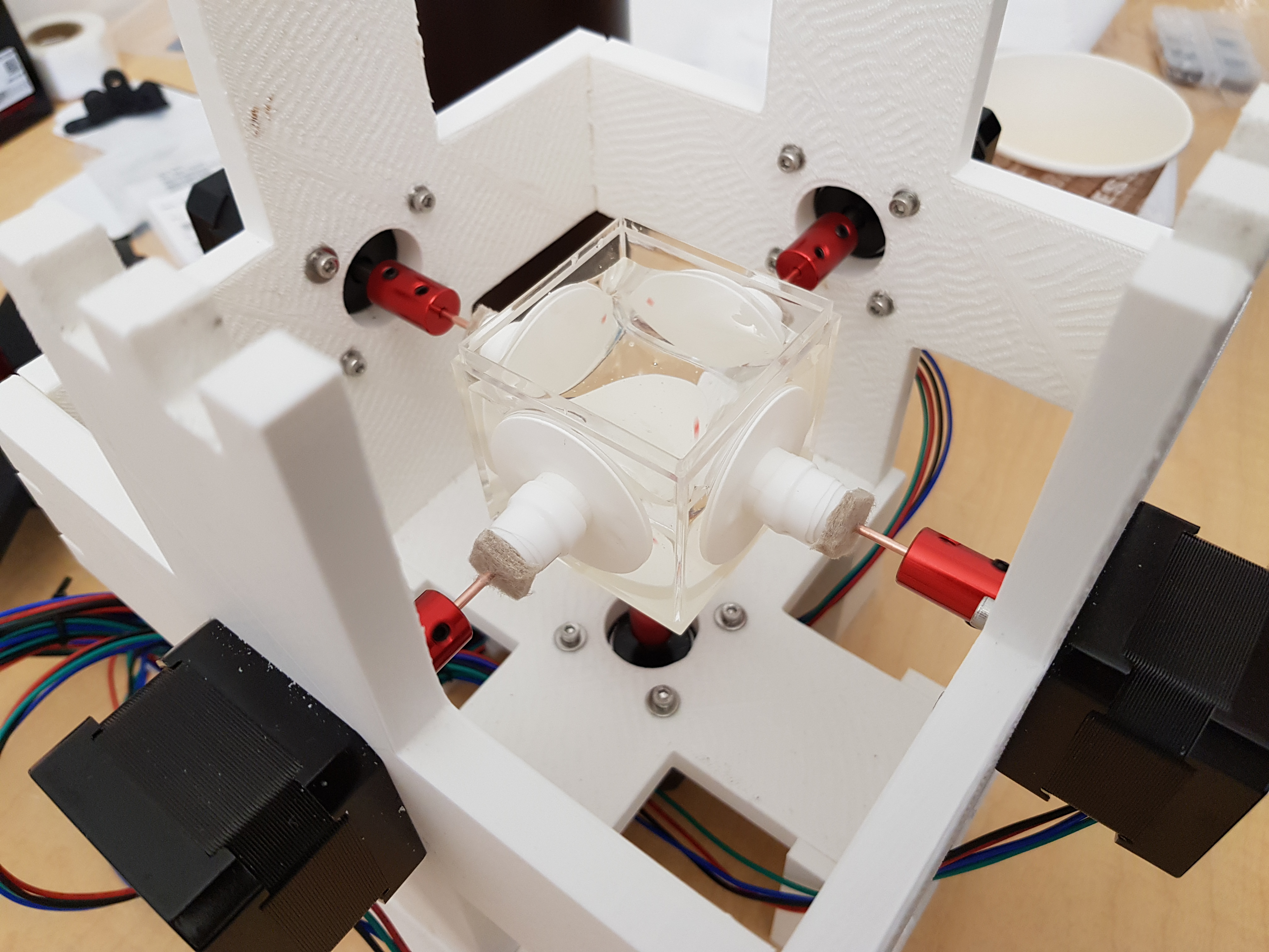
The chamber and the rotating disks are the central element of this robot. The main challenge was to have thin disks that were inside the chamber, but able to rotate reliably with no leaks. Due to the highly viscous liquid (glycerol) inside the chamber, rotating the disks requires a large torque. On the left was the first design: each disk is 3D-printed and linked via a thin rod to a shaft coupler that attaches directly to the motors. The first tests were rather unsuccessful: too much wobbling (due to the thin, flexible rods that were not well aligned with the motors), a bit of leaking, and sometimes the disks would stop rotating due to the thin rods slipping from the disks or from the shaft couplers. We updated the design to address these problems. The solution was to have a more flexible connection, as shown below.
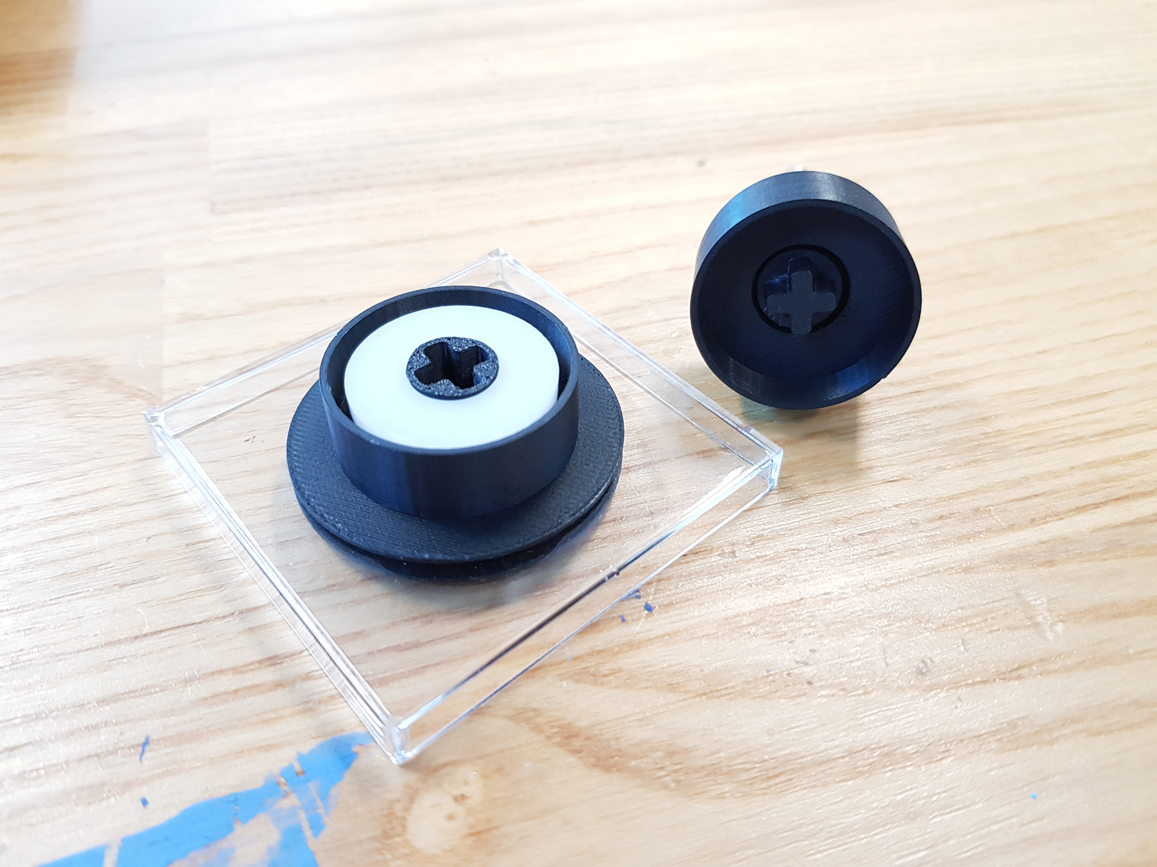
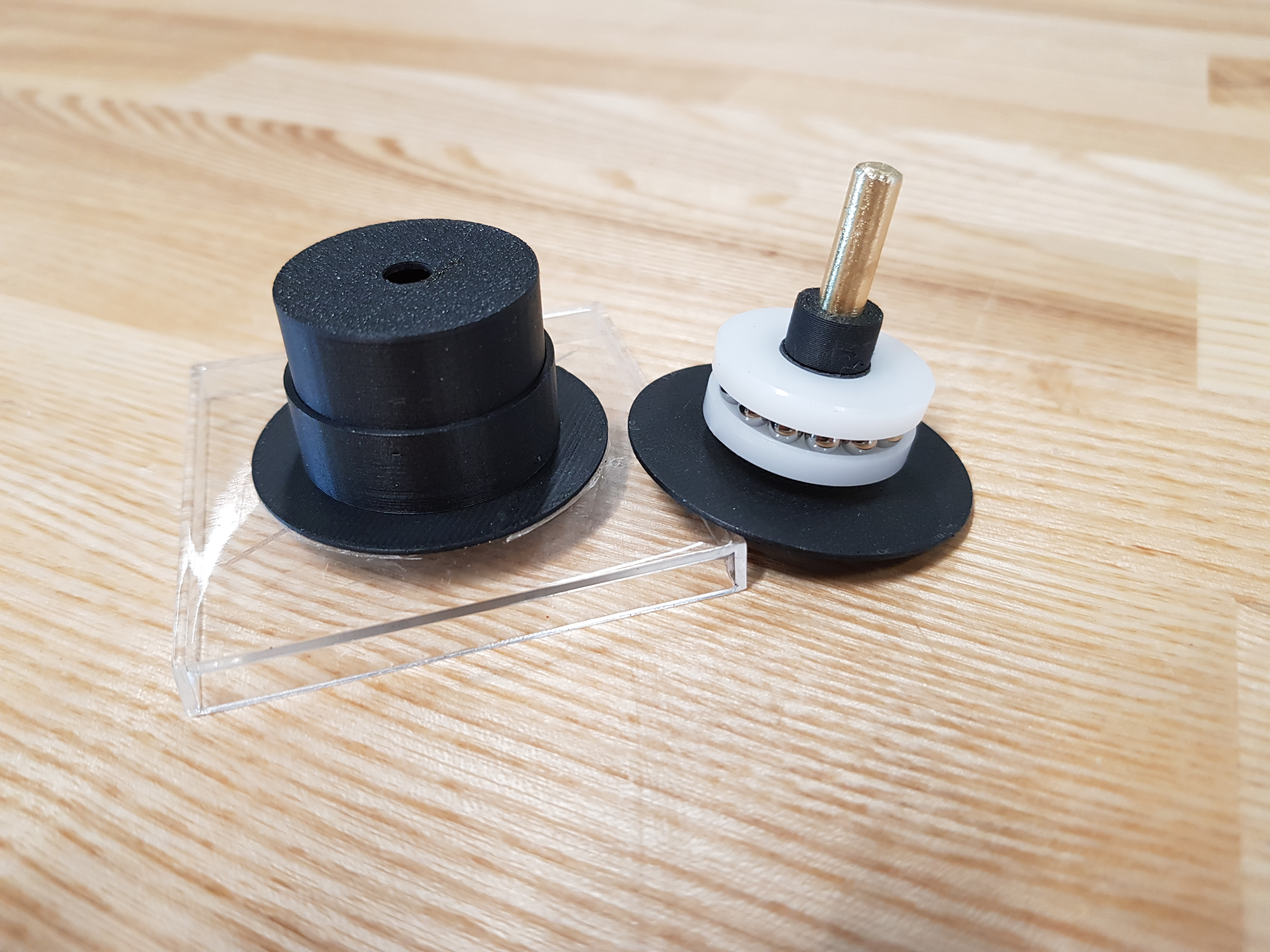
This new design uses ball bearings to ease the rotation of the disks, and a cross-shaped connection that allows a more flexible connection with the shaft coupled to the motors. Furthermore, the frame responsible to hold the motors, initially built from a plastic box, resulted in bad alignment of the motors. Below are pictures of this first frame:
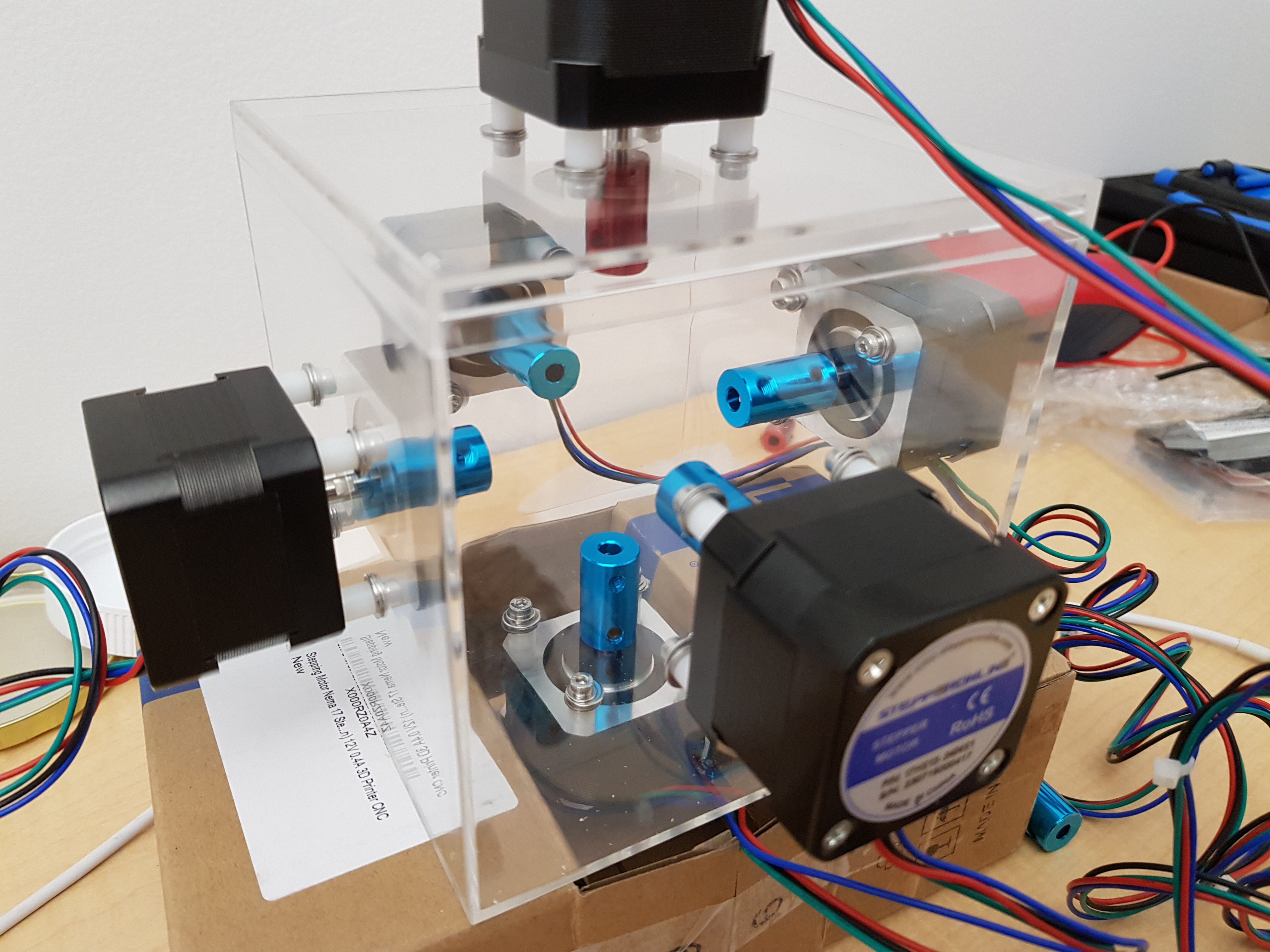
We decided to redesign the frame to make it more robust, provide a better alignment, and more space to access the chamber. Below are the results:
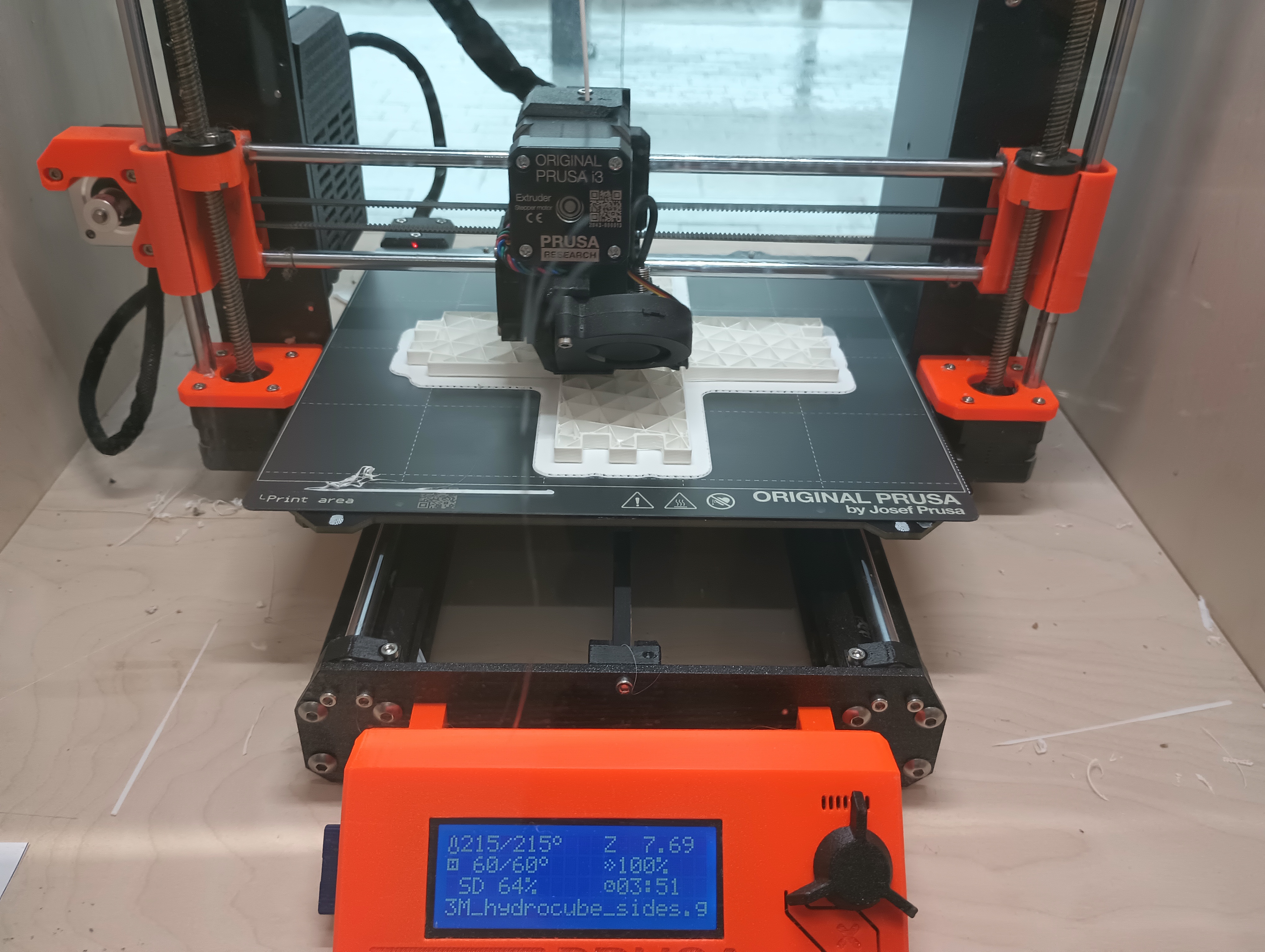
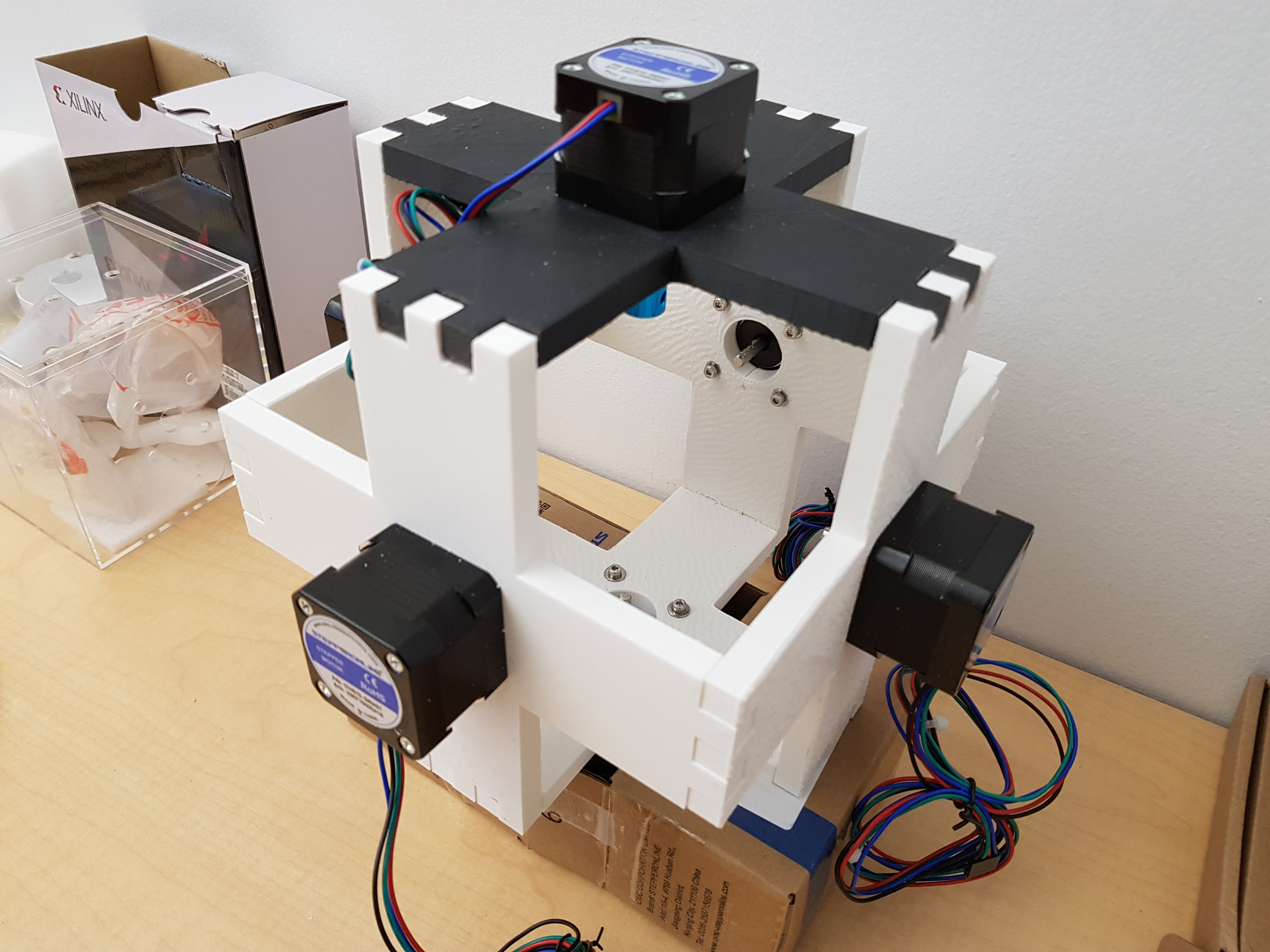
Note that these are the largest pieces we had to print for this device, and also the first 3D-printed pieces we ever made. These were all designed with SolidWorks, with a license provided by Dassault Systemes.
Electronics
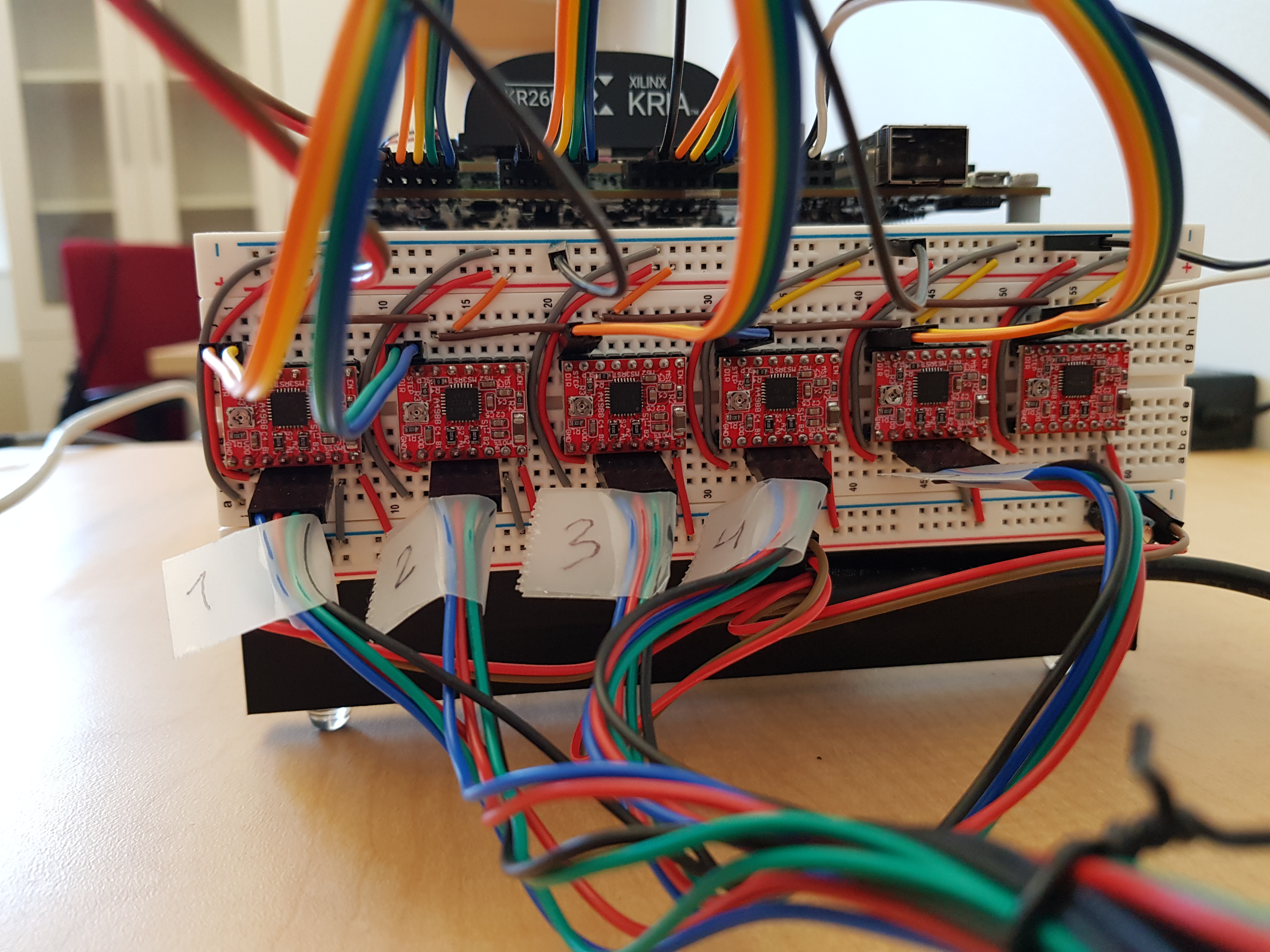
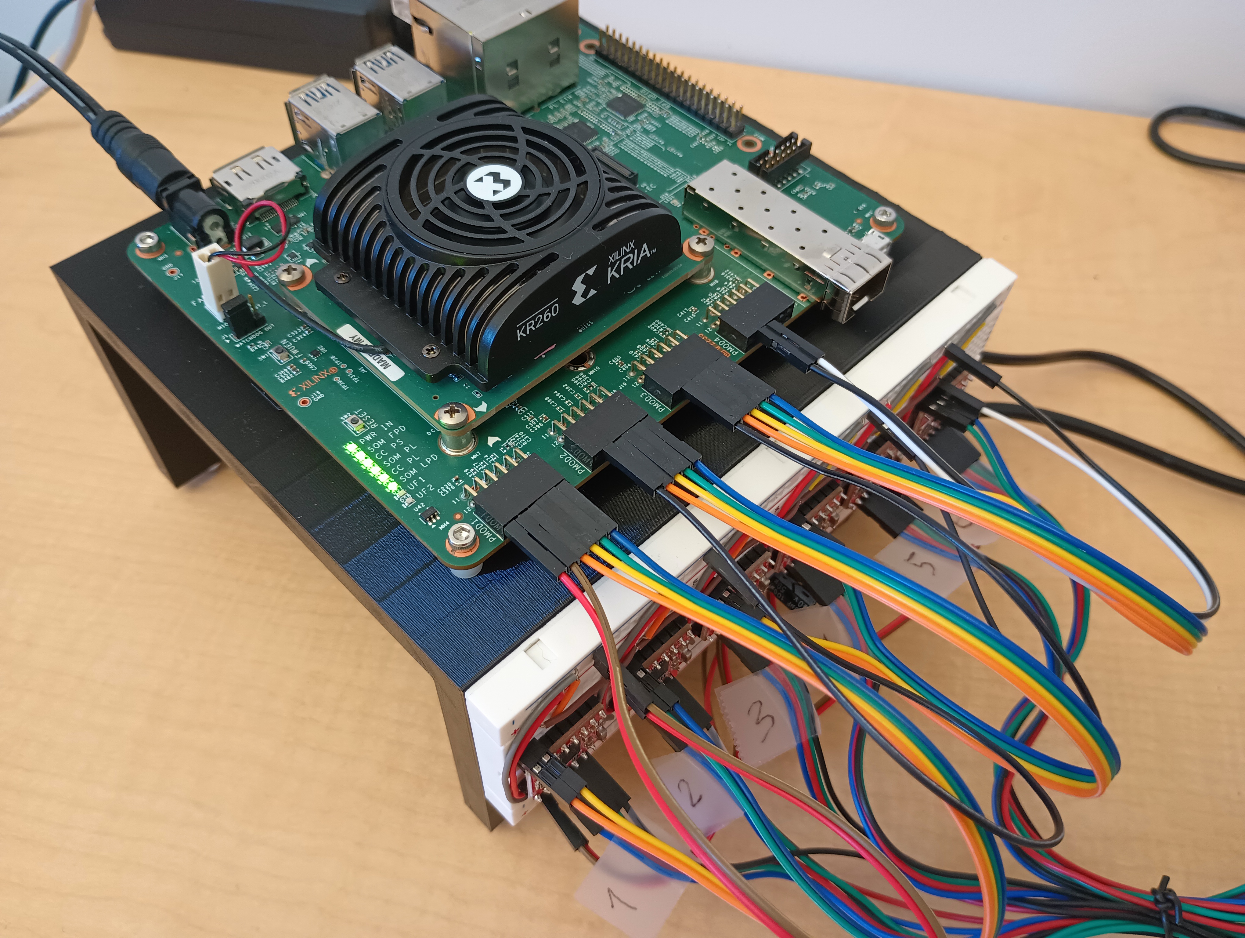
To rotate the disks, we chose Nema 17 stepper motors, which only cost a few dollars and have a large enough torque to sustain disk rotation in highly viscous fluids. We connected them to the PMOD of the Kria board (provided by AMD, one of the sponsors) and to an external power source. To do so, we used A4988 drivers, leading to many electric connections. We first opted for bread boards during the prototyping phase but ended up keeping those in the final design due to the time constraints.
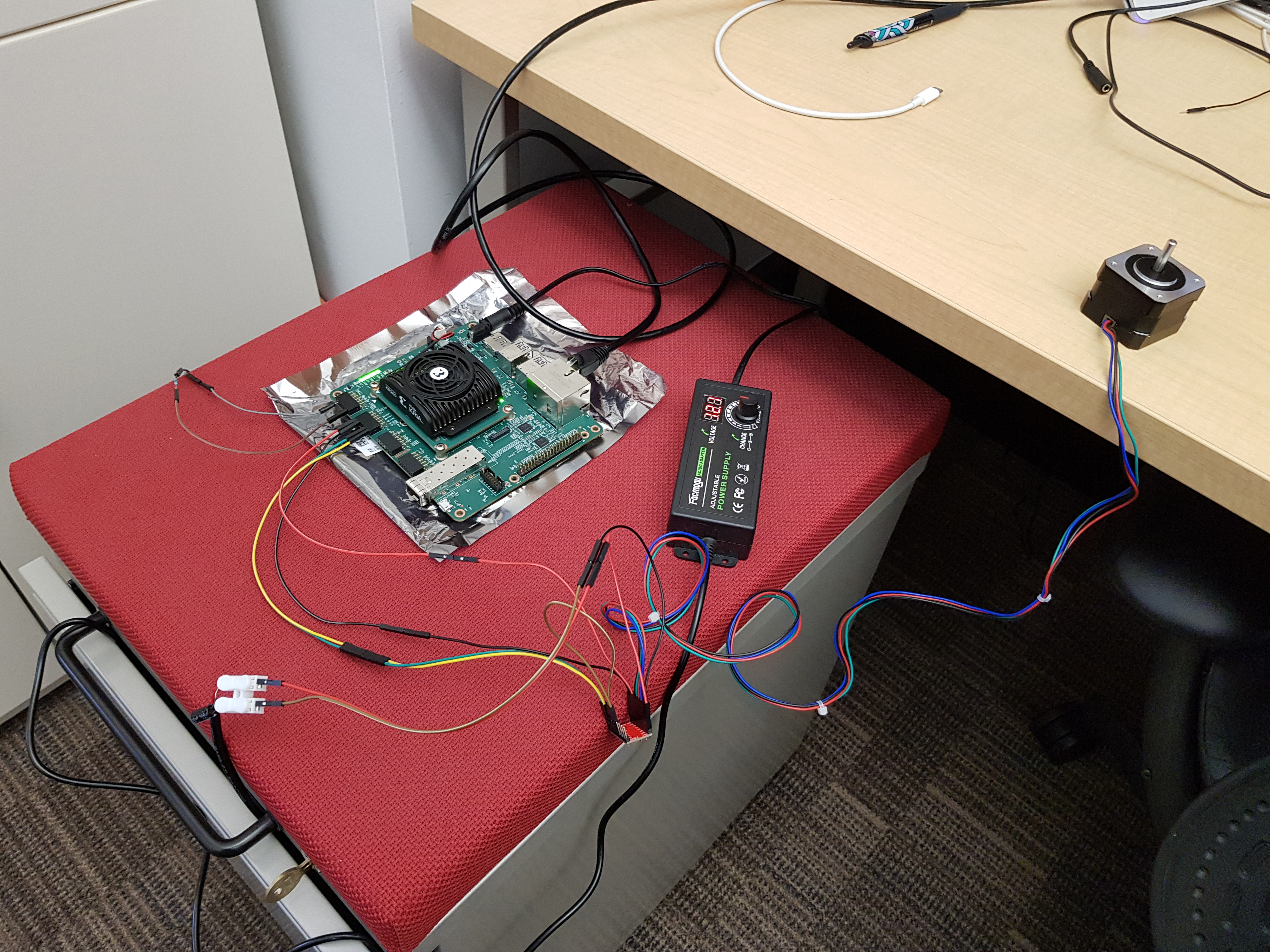
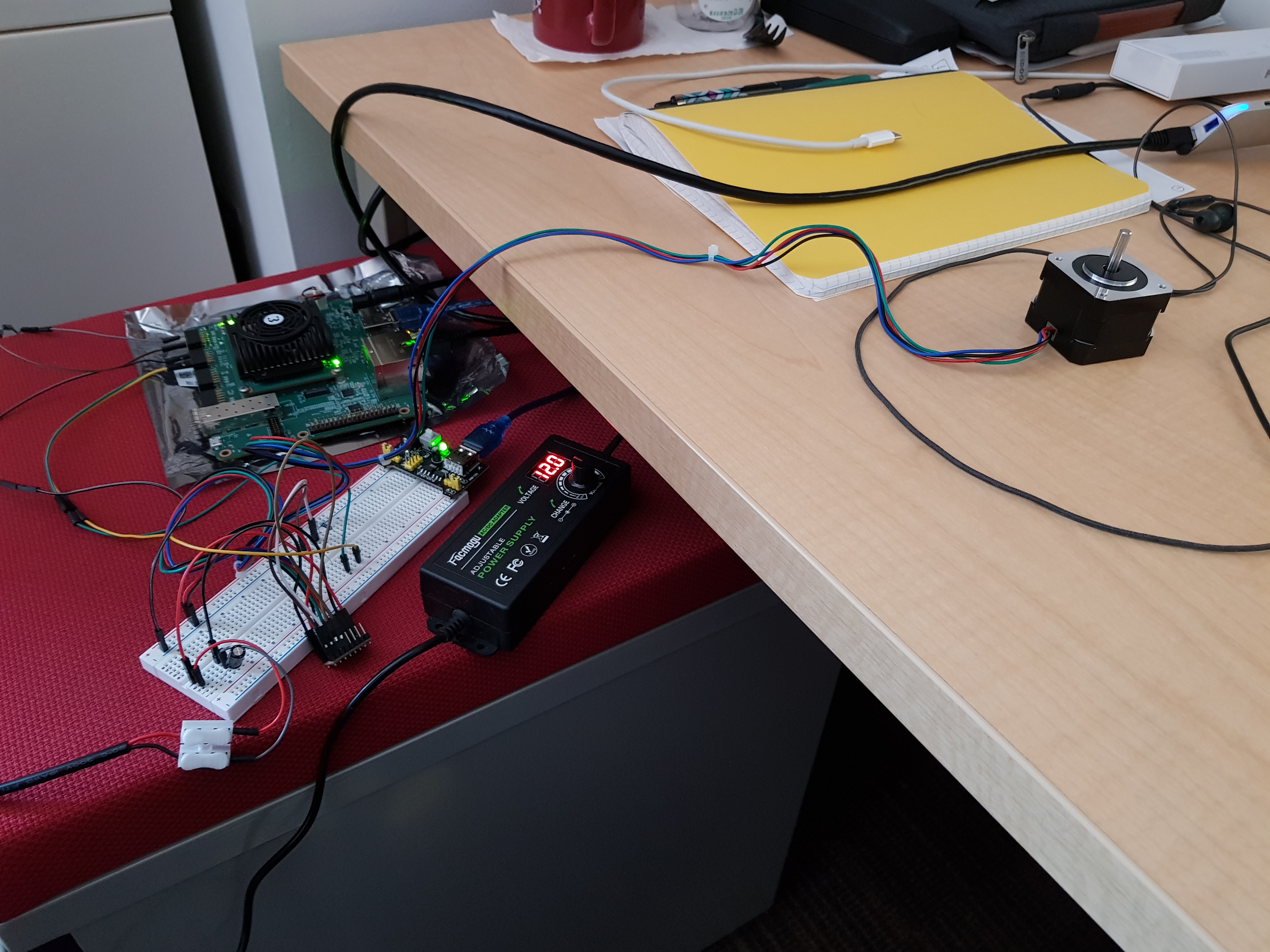
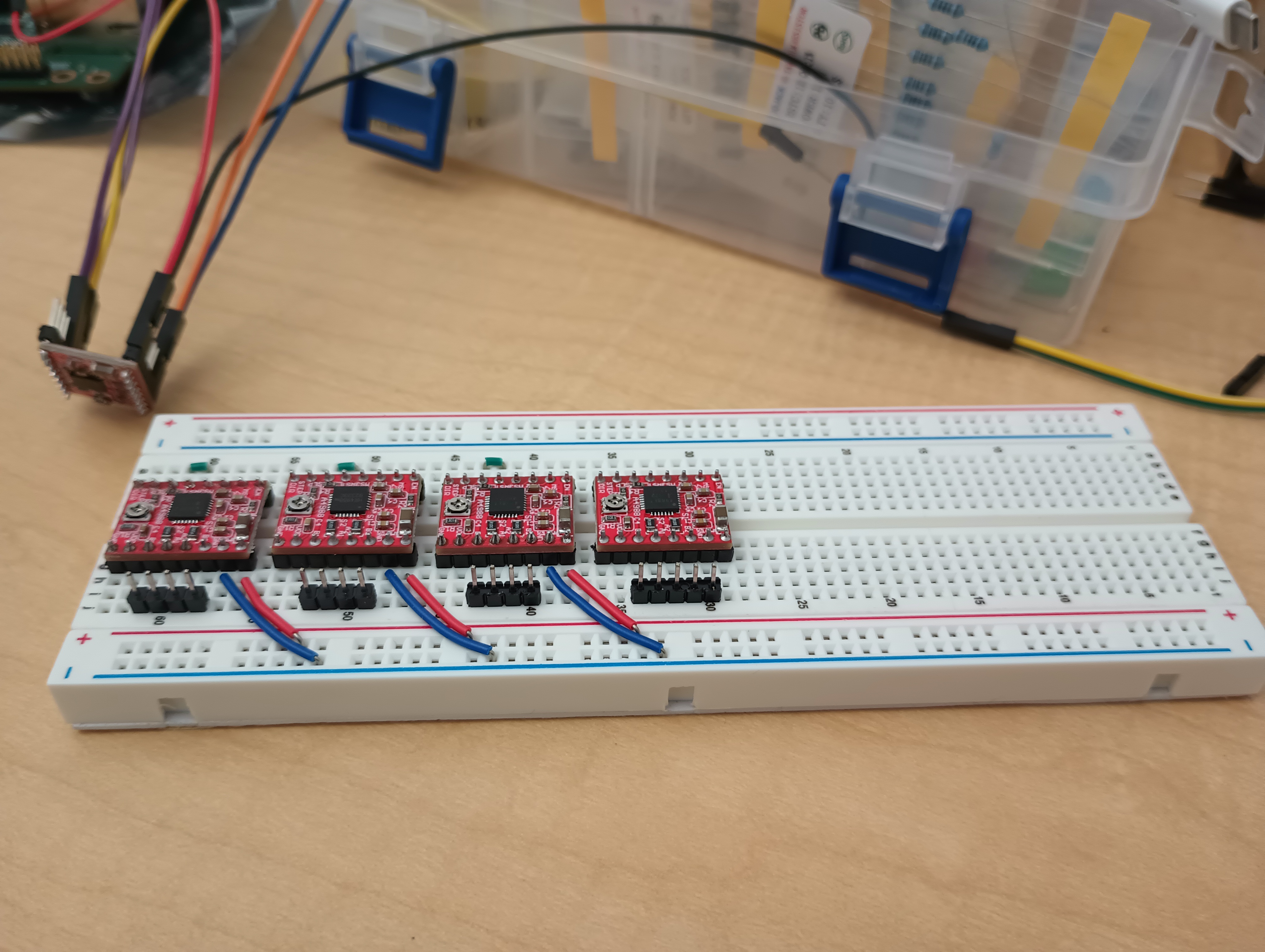
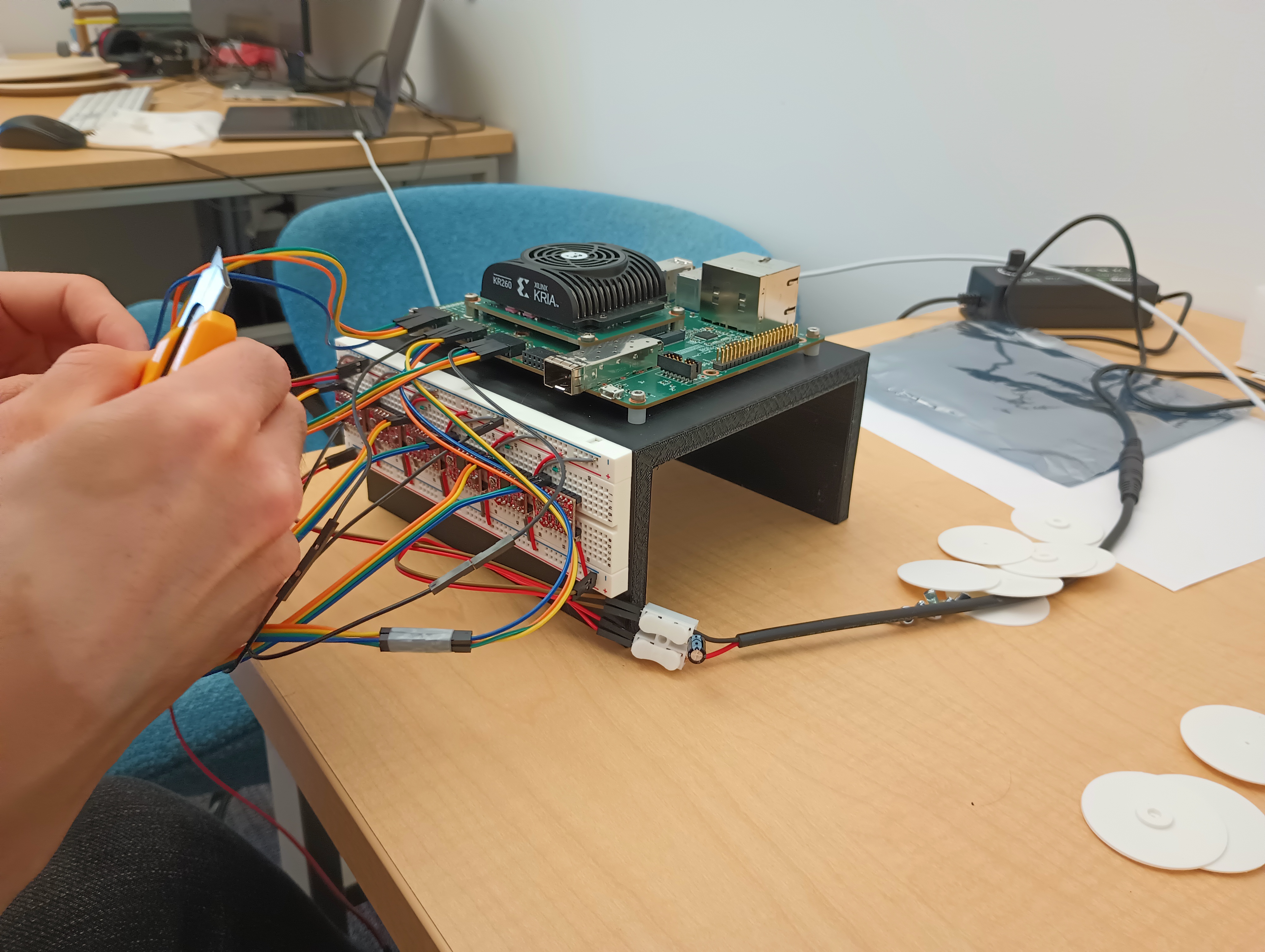
Once everything was connected to the breadboard, things look a bit messy: many long cables between moving parts, making the whole thing rather fragile. We thus built a new frame to organize all the electronic components: the Kria board on top, attached with screws, and the breadboard on the side, attached with double face tape. The power cable was also attached to the frame to avoid non-intentionally pulling on the connection.
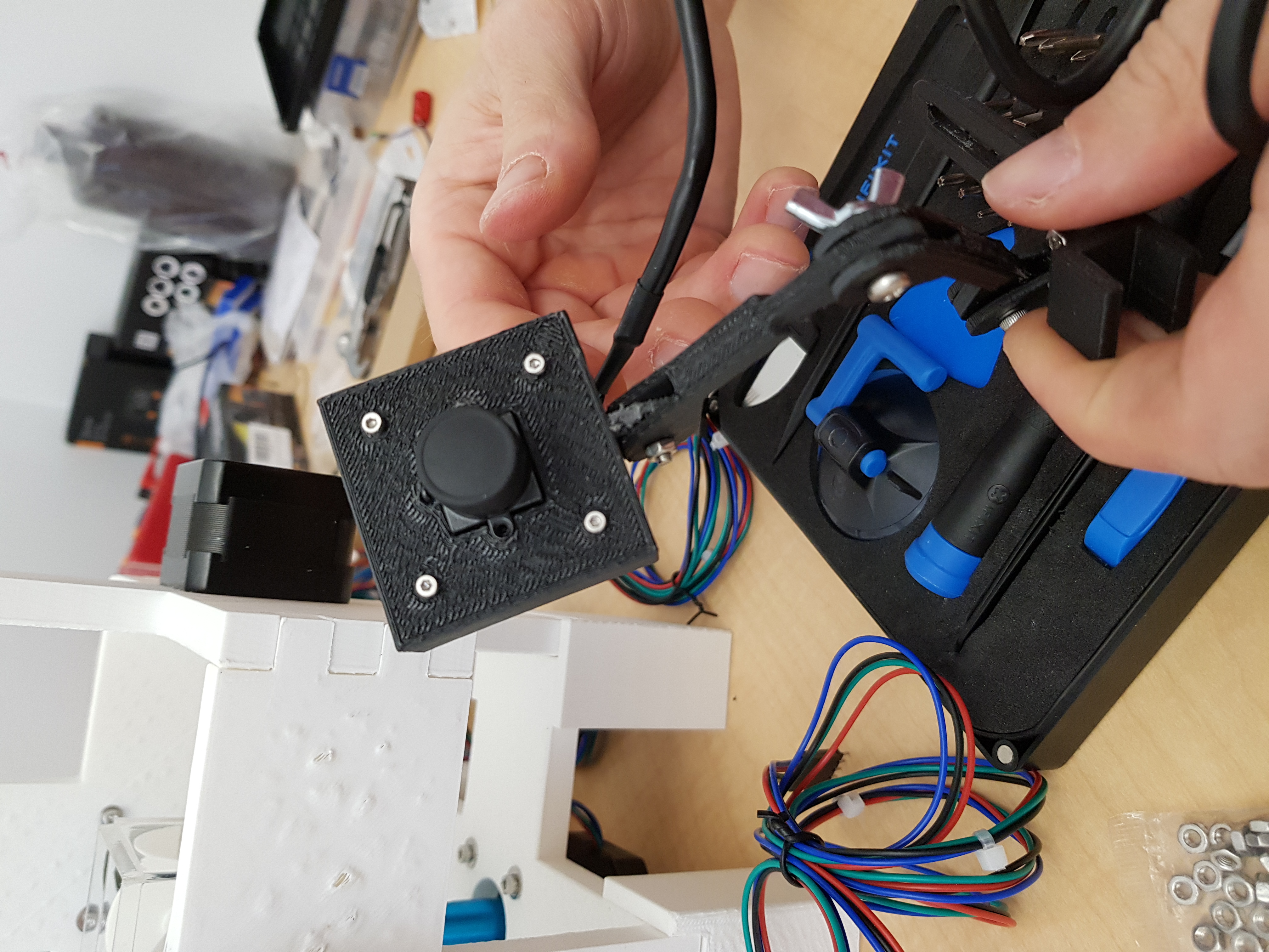
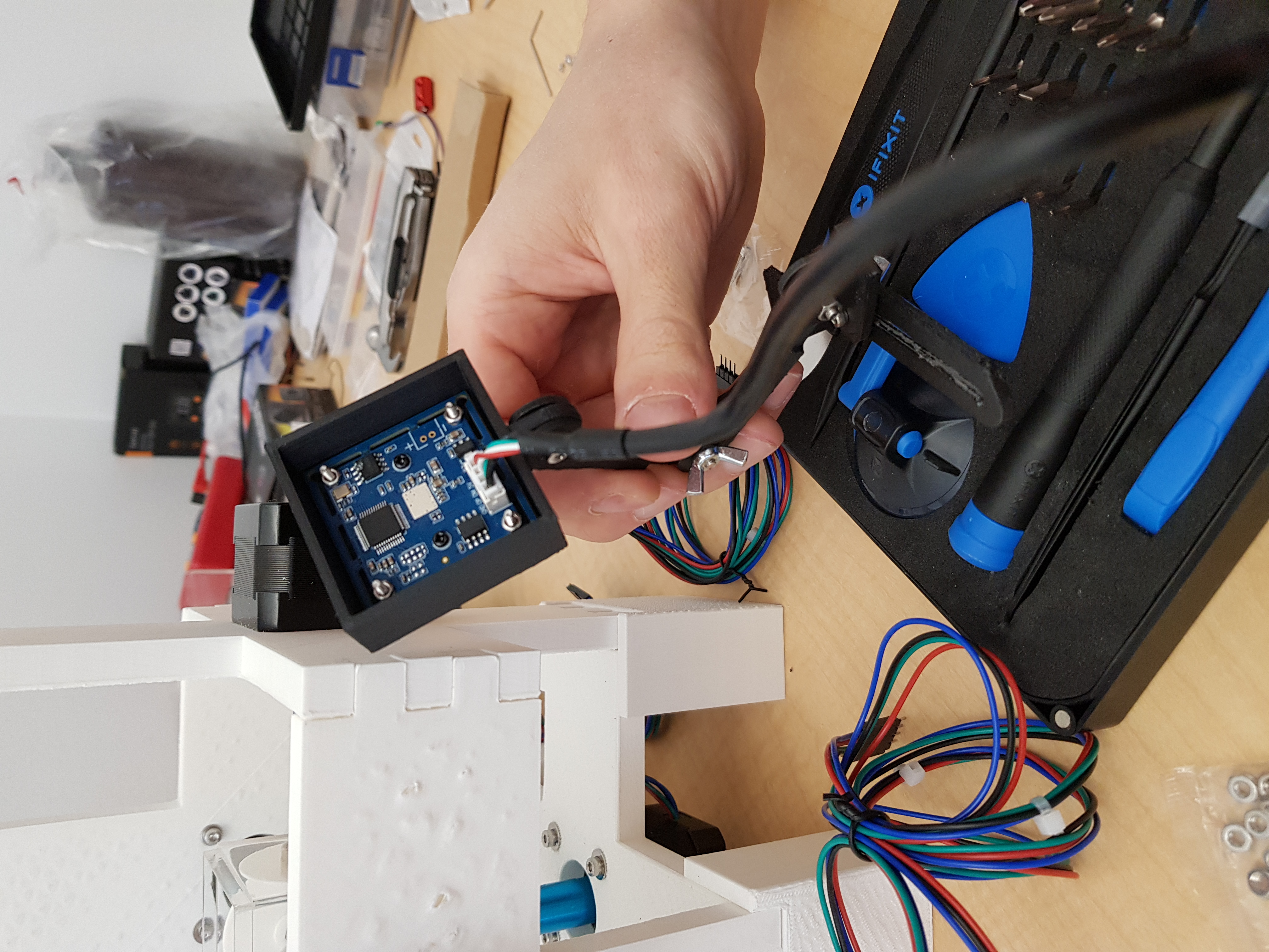
Cameras and vision
The last main component is crucial: giving sight to the device so that it has feedback. The aim here is to estimate the 3D position of the suspended beads, which requires at least two cameras. Reconstructing the position is then a mix of tracking of the beads in image space and pose estimation of the cameras, taking into account the refraction of light between glycerol and air. It wasn't clear how to optimally place the cameras within the frame to have a view of the whole chamber from both cameras. We thus designed a camera frame attached to movable arms, so we could adjust the position of the cameras:
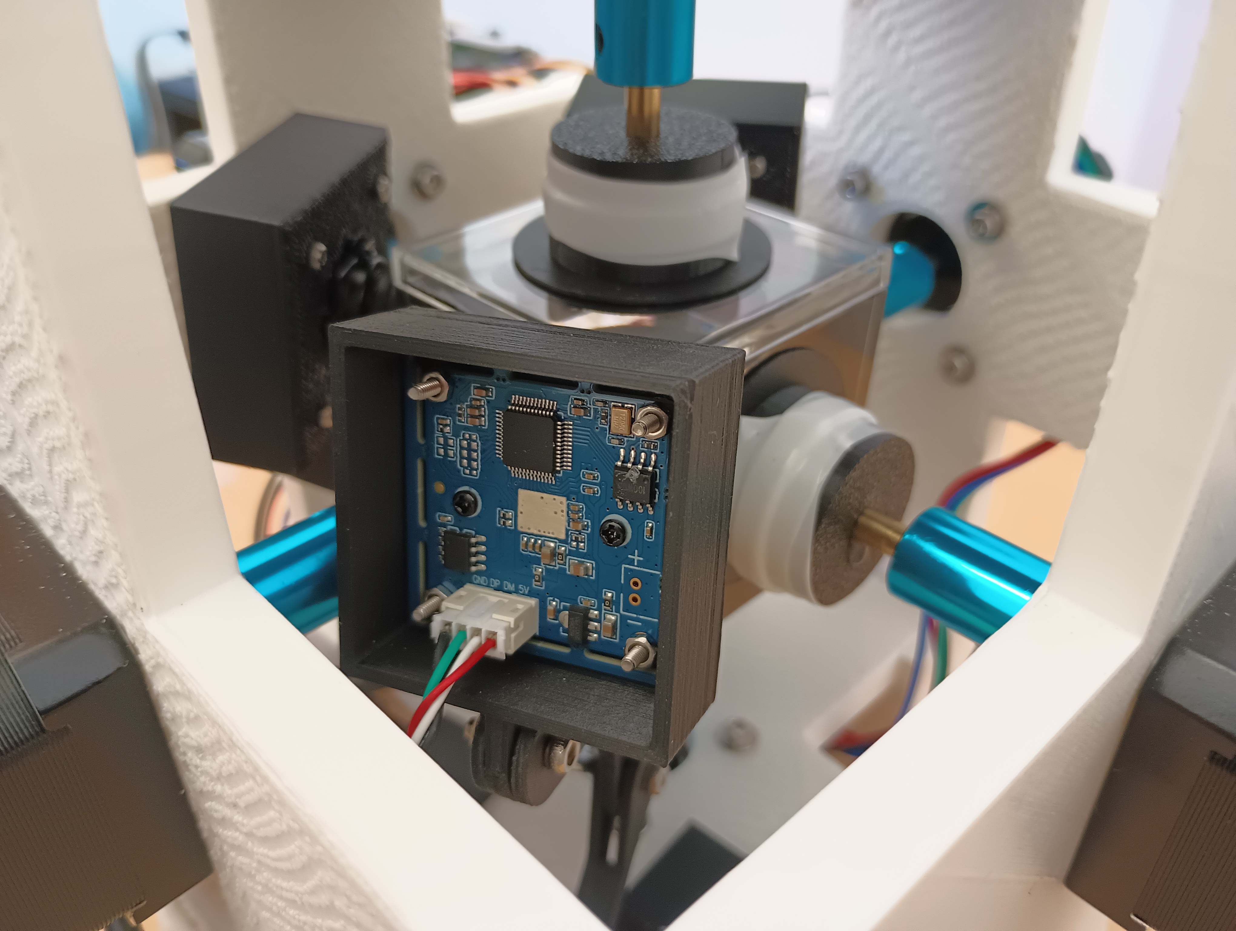
There was then an algorithm to infer the positions of the cameras from reference points on the image. We then implemented an algorithm to track the beads and estimate their positions in 3D based on the 2 images. This position was then fed to the policy neural network learned by the ODIL method, as explained in the article.
D-day
With all these components put together, the hydrocube was ready to be presented at the robotics summit. The event lasted 2 days and we had a small booth with a poster, the hydrocube in action, and a computer screen showing the view from the cameras and the 3D reconstruction of the chamber, showing the current disks rotation speed and the beads positions.
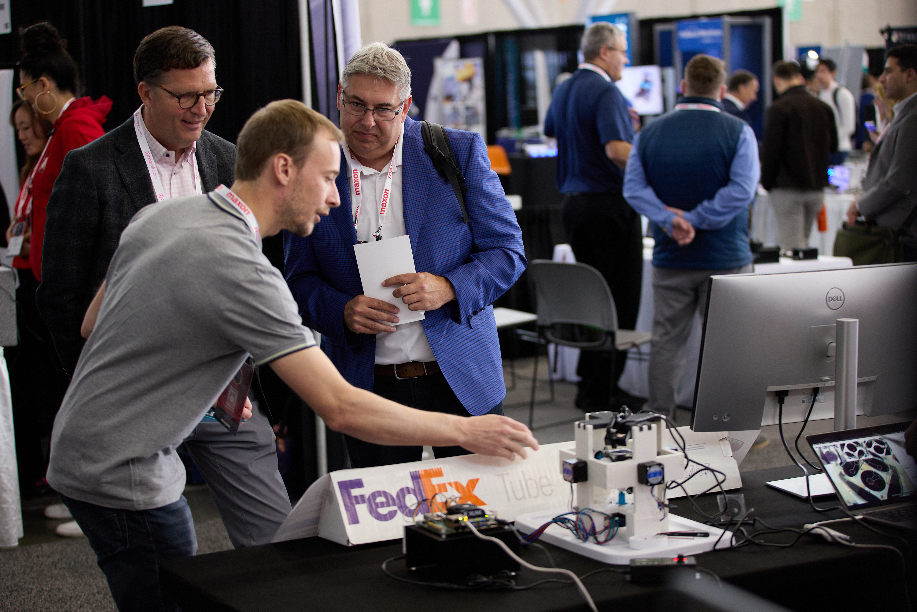
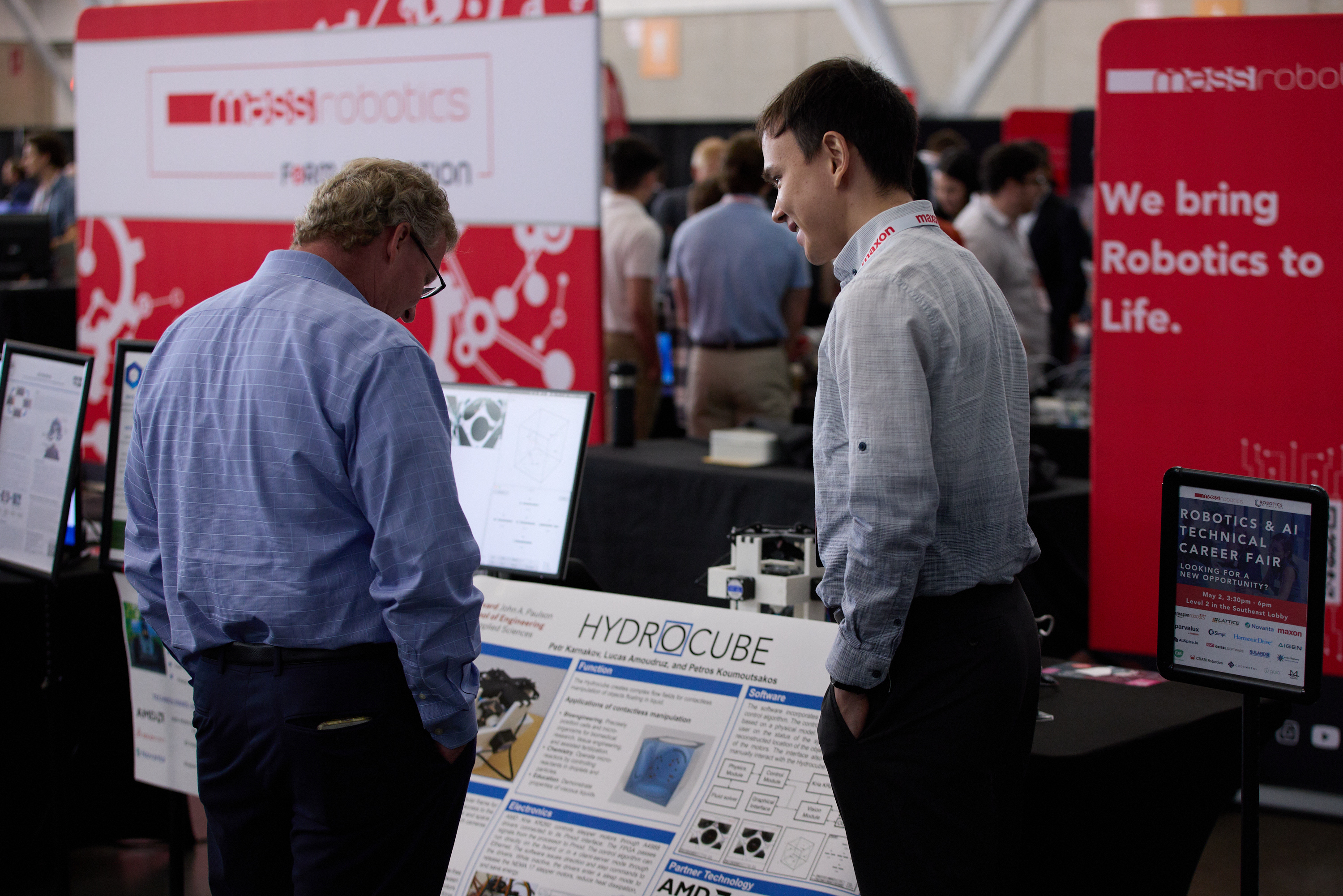
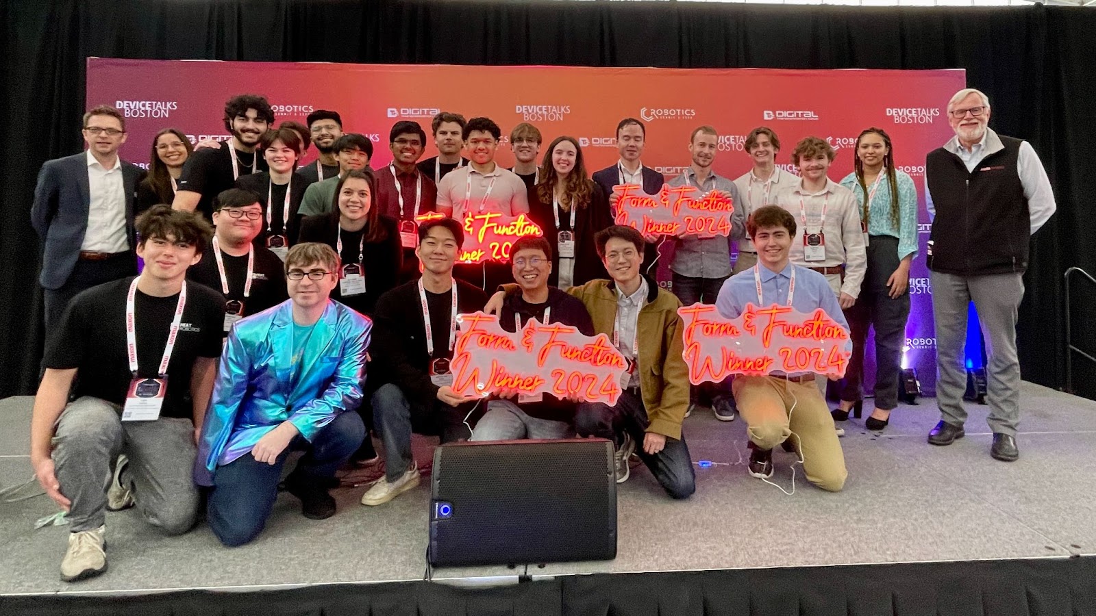
The robot generated quite a lot of interest, mainly due to its originality, since the main component here relies on fluid mechanics. These two days were a lot of fun as we could finally see the robot in action (it was still not fully functional the day before) and many curious attendees. We ended up second at the robotics competition, despite having only 2 months for building it and our lack of experience and knowledge in building electronics, 3D printing, FPGA programming, and vision tracking.
What a great and exciting experience! It's rare to see my numerical work directly applied to a real-world setting, and it was almost surprising to see how well it works given all the approximations we had to make during the simulations. This is very promising for other applications and I can't wait to apply this method to even more complex systems.